


EngineerX
-
Posts
23 -
Joined
-
Last visited
Content Type
Profiles
Forums
Calendar
Posts posted by EngineerX
-
-
8 minutes ago, PatchesC said:
There's a good 50 pages in that particular group of plans.
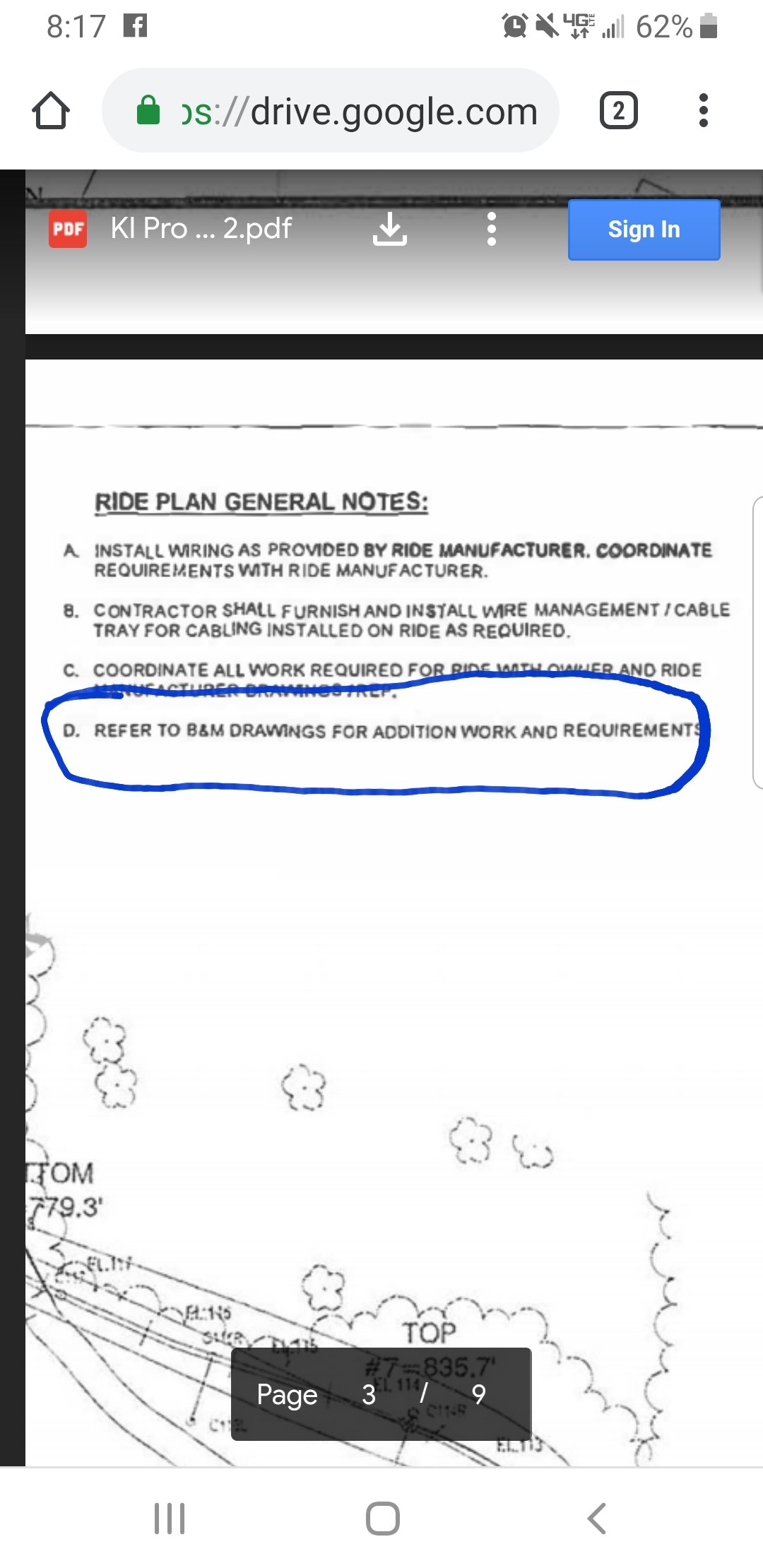
Here is an interesting tidbit on the 3rd page of leaked print, called sheet no. 0-E7.0.
The ride prints themselves are not part of this group.

Excellent observation. Its also worth noting that in the leaked prints the engineer didn't clean up the old rev bubbles as they would for a final release. The leaked prints are likely a cut and paste job providing initial detail for phase 1. IE, clearing the grounds for work to begin.
Once prints are released for work to a contractor doing grading, controlling where they go is near impossible. They don't need structural details for the actual grade work, so it's fairly common practice to issue an "in progress" set of prints to those contractors.
-
 5
5
-
-
Food for thought: Why wouldn't they just file all of the prints at once vs in phases? Considering the first set shows the entire layout, what is left to hide by not filling all of the below grade prints?
-
2
-
-
1 hour ago, fyrfyter said:
It’s over. If there’s a stamp on the first page, they are approved. You don’t have to stamp every page.
Just because we can’t see a working set, doesn’t mean they aren’t already there.Not true. Every print must be stamped by the engineer that made or reviewed the drawing. The only exceptions are for preliminary or draft drawings. All final drawings, or prints issued for construction must have the responsible engineers seal, signature and date.
-
5
-
-
Riddle me this. Is it cheaper to fix a coroplast sign with an extremely specifically designed tape, or reprint the poster?
Why would they continue to make mistakes and not proofread their work?
Again, these "mistakes" are significant.
-
7
-
-
1 minute ago, fryoj said:
I'll make sure I go tell those guys that actually know what they are doing that someone on the internet said they were wrong.
Just don't tell the guys that call them "foundations". Which is a more common reference than both.
*and yes. I know the difference between footings/footers and foundations. Just saying the guys doing the work, or even designing them use it interchangeably
-
2
-
-
1 minute ago, Jallie79 said:
I have a hard time believing that the first 2 posters were misprinteed. Especially now that the FoF poster has changed. If the Bayren Kurve poster changes tomorrow, I all but guarantee that the changes are significant.
Is anyone able to post every version of each poster in one post to look for clues as to what has changed? I have pics the way they were yesterday around 1700 when we were there.
This guy gets it.
-
2
-
-
Hmmm. I wonder what the significance of the posters constantly changing can be....
-
4
-
-
@MrSourNinja just saying there are more answers there, but not the scale. That was an oversight that has turned into the biggest red herring.
-
5
-
-
2 minutes ago, fryoj said:
I get being disappointed and wanting something more, but, like you said, you aren't an engineer. Engineers and people who understand plans have looked at these and no one is concerned with the scale being off.
Engineer here. You are correct about the scale. No one looks at those anyways. When I was a designer, 95% of the time i didn't even include the scale in my title block unless it was there by default in the customers template.
-
4
-
-
2 minutes ago, Enchanted Voyage Lover said:
I'm sorry. I think this is going to be taller than what I'm seeing predicted. We know the scale on the plans are wrong. From scale measurements I'm taking from the footer 53.5 on the plans, (which is 25' 6" long) it looks to me like the lift hill distance from beginning to top is closer to 375' as opposed to 340' long. That means the height would be between 310' - 315', depending on the actual distance. I used the ride electrical partial site plan area 1 to get my scale measurement of 53.5, and then lift hill which shows the beginning footer and top of hill on it. Anybody out there is welcome to check me on this, I'm not an engineer.
There's something everyone is missing. You're on the right track.
-
10
-
-
Something that i eluded to waaay earlier, but the posters changing mid morning is significant. Things aren't always as they appear. Hint hint. Prints. Wink wink.
-
5
-
-
3 minutes ago, Bwb.32 said:
The most typical output of saving a cad file is well ofc a cad .dwg file, and right behind that PDF so it wouldnt suprise me that its a PDF export of the cad file. Not to mention it just looks like a cad drawing.
Exactly. Anything issued for actual work will be a pdf. The actual cad files will be reserved for the engineers and designers. Any markups will get made on pdf/paper and returned to the designer, to update the record prints (cad).
So not only is a pdf not surprising, it's expected.
The bigger question here is, do we have a full project, or do we have a phase 1 that is the bare minimum to start work.
-
4
-
-
2 minutes ago, DonkeyKong said:
I would just like to present my view points about the "leaked layout" that I am unsure of.
1) Out of all the companies that have access to the proprietary CAD file, I would assume that only people of management type (or in general not you average laborer) have access to said file.
2) Assuming my first point then we have to accept that somebody with a decent amount of responsibility within their company who would also know the repercussions elected to leak the files on KIC
3) I'm not sure what the "leaker" stood to gain from their actions especially when you take into account their nonchalant responses after their leak. They immediately acknowledged that people shouldn't look at it because it was private, and then essentially laughed at the person that questioned the validity of their leak. So they leak the layout, admit they did something wrong, and then stand by their error?
4) How did this person know to come to KIC only moments after the legitimate blueprints were shared with the community? It seems like an unbelievable lapse of judgement, almost premeditated which would mean this person working for whichever contractor potentially a member here.
5) Lastly are we to assume that of the few companies/people that have access to the CAD Files one vigilante decided to leak it here of no gain to themselves other than reeking havoc.
I fully understand that the majority of the evidence points to the leaks being reliable, but I still have my reservations. I'm not calling for a full out conspiracy theory but there are some holes here maybe someone can answer them.
You make some valid points, but you greatly underestimate the number of designers / engineers that are required to have access to the full drawing set.
-
5
-
-
9 minutes ago, RuthlessAirtime said:
I gotta say, I am seriously enjoying the levels of conspiracy and mystery surrounding the hype for this ride.
”Giga-Gate” has gotta be one of the most contentious lead-ins to a ride announcement and I’m loving it lmao
It's only going to get better from here.
#OpLilGiga
-
7
-
-
2 minutes ago, presto123 said:
Exactly who would have leaked the layout? Why would somebody who signed a NDA risk being found out and sued by the park/lose their job so they can leak some plans that only coaster nerds care about at this point. All of this while getting ZERO credit/compensation because they have to remain anonymous?
Because they are nerds too.
-
1
-
-
7 hours ago, befat said:
B&M (almost) always starts construction with the transfer track, station, and lift. So if KI could try to avoid the layout going public for a little while by filing a partial print, why wouldn’t they? If I remember correctly, there was construction going on all over the layout for MT from the beginning which could explain why they had to file the full print of the layout.
You mean like a layout plan being issued to the contractors doing the clearing / grade work that is likely to be leaked? You think they might anticipate that and release a "phase 1" printset that looks complete to start the project while mitigating leaks. Yep, that's just crazy talk
")
-
2
-
-
7 hours ago, RuthlessAirtime said:
Do you work in power engineering? This strikes me as the type of intuition only a substation engineer would have
Electrical engineer by trade. Worked specifically on power transmission / distribution in a past life (utility sector), but not currently. Now my expertise is controls and automation (outside of the utility industry).
-
1
-
-
1 hour ago, Thane Of Price Hill said:
Not sure that would provide enough current. According to this https://www.coaster101.com/2016/07/20/coasters-101-launch-coasters-store-energy/, a regular lift hill motor works on about 200 amps while a launch could use up to 4000 amps.
That also explains more about how various launches work such as Thunderbird, Incredible Hulk’s original launch, TTD and Lightning Rod.
Meh. They would typically use a capacitor bank rather than put that amount of current onto the electrical system. It's really difficult to coordinate the power system constantly putting 4000A on all at once. Not to mention the cost building the infrastructure to handle it.
-
2
-
-
2 hours ago, Ben43065 said:
I’m sorry but if this giga coaster is suffering from “Budget constraints” a launch lift hill would make absolutely zero sense. As cool as it would be there’s a 1% chance they’d actually do it.
Nailed it.
-
1
-
-
2 minutes ago, kissfan4 said:
I pointed this out earlier today, which is probably 20 pages ago, lol. In my head i see the face that the backbone is bolting to set to 50 degrees, and assuming the base plate on the backbone is welded on square, when it is bolted to the face it would be perpendicular, therefore set to 50 degrees. Does anyone have any documentation that says the lift hill angle is always referenced off the angle opposite where the backbone bolts up?
It's referenced from its angle to the ground. Therefore, 40°. The 50° is the angle of the backside of the plate, not the hill itself.
-
1
-
-
Don't forget. For early stages of construction for "secret" projects drawings are often drawn as "complete", then updated later to reveal more and more of the project.
A lot of workers get to see these and its expected that they will leak. So only in the know, critical designers, engineers and approvers see the true completed project this early.
-
7
-
Decoding 2020
in Kings Island
Posted
They can file the SWEP permit under multiple names, even like to a random person like a project foreman. Alternatively they or the contractor doing the work may have their own environmental group and self permit / report.